I was already thinking about AI predictions and remote control before I’d managed to get a useful reading from a solar inverter.
What even is a solar inverter?
Now, you might be wondering, what even is a solar inverter? If you already know, feel free to skip this little masterclass.
Solar panels produce direct current, or DC, while most household appliances use alternating current, or AC. The inverter converts one into the other, so the electricity from your solar setup can power things like your TV or fridge.
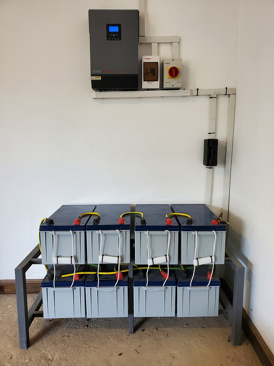 A solar inverter (top) and its battery bank in Kenya. Photo: PowerAfricaSolar, CC BY-SA 4.0

Depending on the model, it can also manage power from batteries and the grid. Many have a small screen showing information such as battery voltage, power output, and faults. That screen matters to this story: the equipment already had information I wanted. I just needed a way to read it elsewhere.
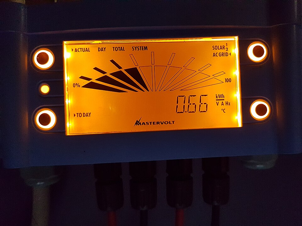 The information is already there, on the inverter’s own screen. Photo: Asurnipal, CC BY-SA 4.0

What I was trying to build
Now that we’re on the same page, the idea behind my university project, which I called SolarEase, was to bring readings such as battery voltage, power output, and faults from the inverter to an app on your phone. You could check how your home solar system was doing without going over to the equipment and working through its display.
Monitoring apps existed, but often only worked with certain inverter brands. I wanted to check my solar setup from my phone, wherever I was: see the latest readings, look back at its performance, and check the weather forecast. I wanted it to work across brands too. Eventually, I hoped to add AI predictions for energy production and possible faults, and perhaps control the inverter remotely.
At the time, that didn’t seem quite as ambitious as it sounds now. I’d seen the communication ports and assumed getting the readings would be a bit like plugging a USB drive into a computer. Connect my device, get the data, and move on to building the app.
I’d planned around what I could do once I had the data. I hadn’t given nearly as much thought to what it would take to get it.
Finding a place to start
I had access to three inverters from different brands. Their manuals explained installation and settings, but not what commands to send for a reading or how to interpret the response. For that, I had to look elsewhere.
My plan was to connect an inverter to a small board called an ESP32 using a custom cable. Using Arduino, I wrote a script in C that would send a command to the inverter, wait for a reply, and print whatever came back on my laptop. Eventually, the ESP32 would collect the readings and send them to the app over Wi-Fi. For now, I just wanted to see if the inverter would say anything useful.
The communication ports looked like the Ethernet ports you’d find on a computer. A search led me to trusty YouTube, where people had made their own cables and successfully read data from similar inverters. That seemed like a reasonable place to start.
I stripped Ethernet cables and arranged the coloured wires according to the examples I found. Most sources agreed that only four of the eight wires were needed—two for power, one for transmitting data, and one for receiving it—but they disagreed about where each wire should go.
 Inverter communication ports that look like Ethernet sockets. The labels say RS485 and RS232.
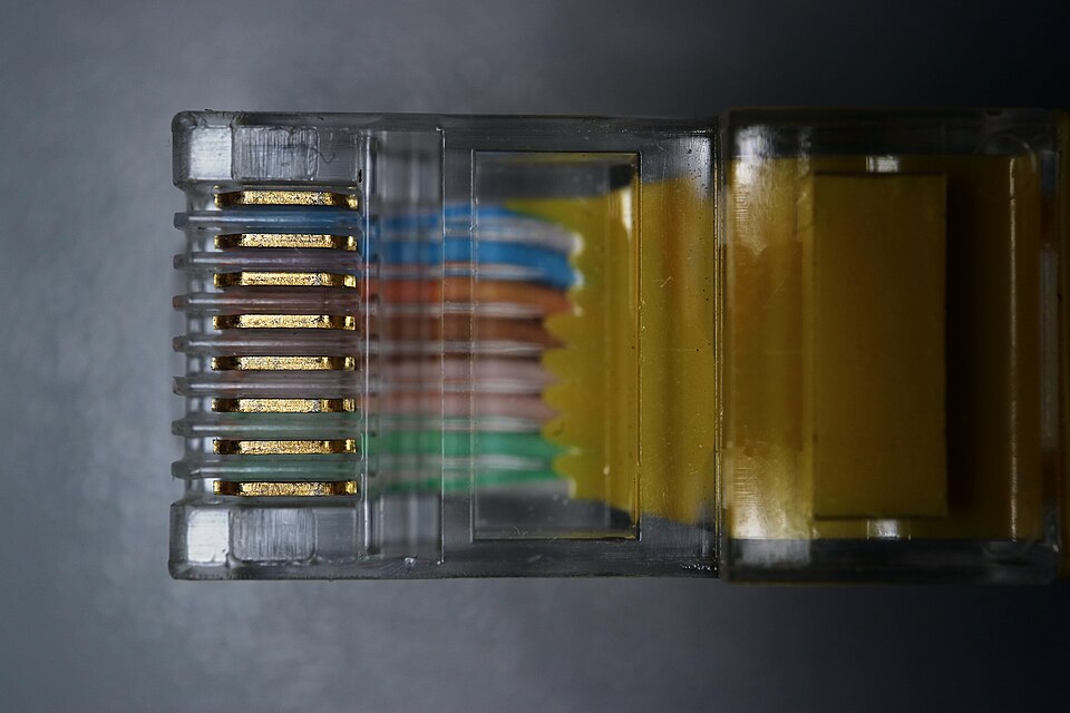 An RJ45 connector: eight contacts, eight wires. Photo: Prosthetic Head, CC BY-SA 4.0

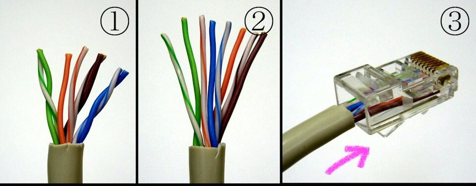 Eight coloured wires, and no obvious way to tell which order is right. Photo: Yqm, CC0 (cropped)

A cable that matched an example online wasn’t necessarily right for any of my inverters. Before connecting one to the ESP32, I also measured its signal voltage. It was high enough to risk damaging the board, so I added a converter between them.
Trying the three inverters
Once the converter was in place, I tried the setup with all three inverters.
Nothing appeared when I tried the first one. That wasn’t much to go on. I didn’t know whether the problem was the cable, the communication speed, or the command I was sending.
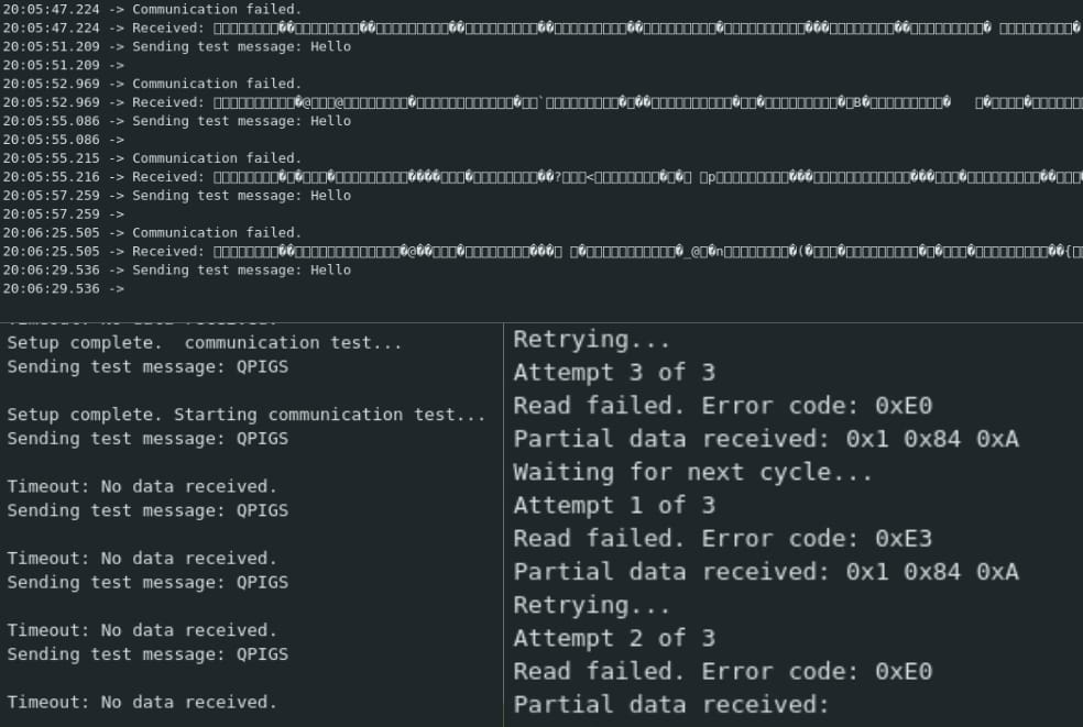
The second inverter gave me something, but the screen was mostly filled with squares and other characters I couldn’t read. At first, seeing anything appear felt like progress. But I couldn’t tell whether it was data in a format I didn’t understand or just the result of a connection that was still wrong.
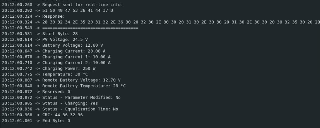
The third inverter seemed more promising. My script printed a list of readings for things like battery voltage, charging current, temperature and status information. It looked like the kind of data I had been trying to get.
But when I compared the readings with what was actually happening, some of them didn’t make sense.
I disconnected the battery, but the data still said Charging: Yes. The output was neatly arranged and looked believable, but I couldn’t trust it. I still didn’t know whether the inverter was sending the wrong information or my script was interpreting the response incorrectly.
I had wanted one useful reading. Instead, I had one inverter that gave me nothing, one that gave me characters I couldn’t understand, and one that gave me readings I couldn’t rely on.
Trying the laptop directly
I started wondering if the ESP32 or my script was part of the problem. So I tried connecting an inverter directly to my laptop with a serial-to-USB cable.
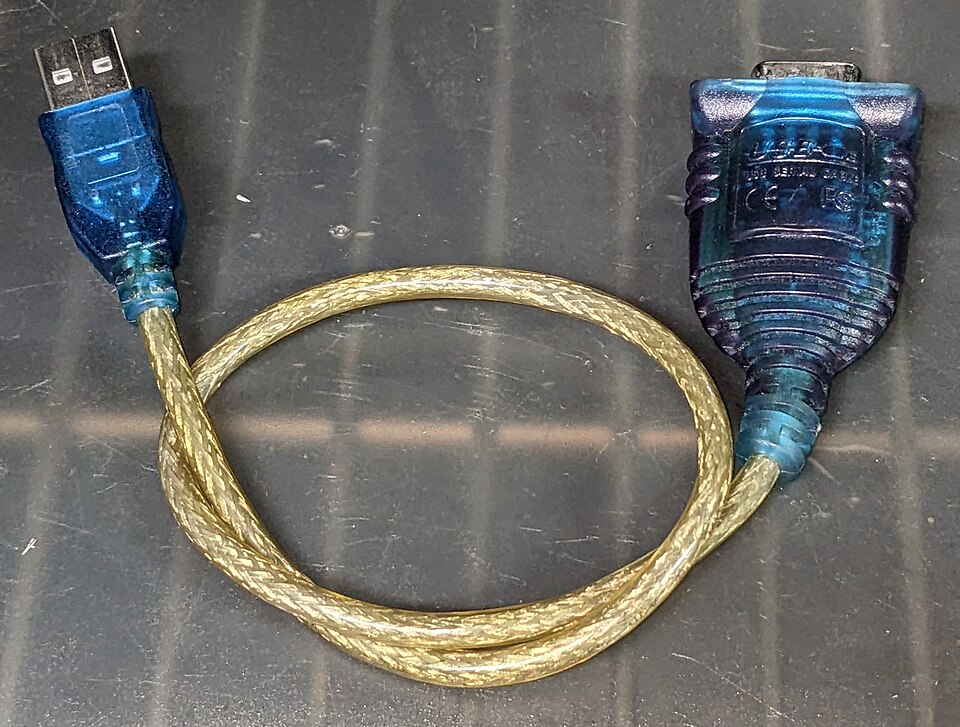 A serial-to-USB cable: USB on one end, a serial connector on the other. Photo: John McMaster, CC BY 4.0

I hoped the laptop would show me the response before my script tried to interpret it. If I could make sense of that, I might have a better idea of what needed to change in the script.
That attempt went worse than the others. The laptop suddenly switched off and wouldn’t turn back on. I could also smell something burning in the inverter. To this day, I have no idea what caused it.
The same port didn’t mean the same thing
Part of what made this difficult was that the ports looked familiar. They were the same shape as an Ethernet port, so it was easy to assume that making the physical connection was the main thing I needed to solve.
I think I was treating those ports a little like USB. When I plug a USB device into a computer, I don’t normally have to work out which pins the manufacturer chose for power or how the two devices should start talking to each other. The familiar connector comes with a shared set of rules. The devices can still do very different things, but the connection doesn’t begin as a guess.
That wasn’t my experience with the inverters. Two of them could have similar-looking sockets and still use different wiring, signal voltages, communication speeds or commands. A cable that worked for someone else’s model could do nothing on mine. That could also explain why people in the YouTube videos got readings while the same approach gave me nothing: their cables and settings may have been right for their inverters, without being right for mine. I had already seen that getting the connection wrong could be more serious than receiving an error message.
Communication standards such as Modbus and SunSpec Modbus exist, but they didn’t solve the problem I had: the three inverters didn’t provide one consistently implemented, well-documented interface. Without that standardisation and documentation, supporting more than one brand meant first working out how each device was wired and what language it spoke, instead of reading a known set of values.
Changing the plan
After all that, I still didn’t have a reading I could rely on, and I needed a way to finish the university project. Eventually, I changed where the data would come from.
Instead of depending on the inverter, I built my own sensor-based prototype to measure things like voltage, current and temperature. Those were measurements I could work with directly, without first having to work out what a manufacturer-specific response meant.
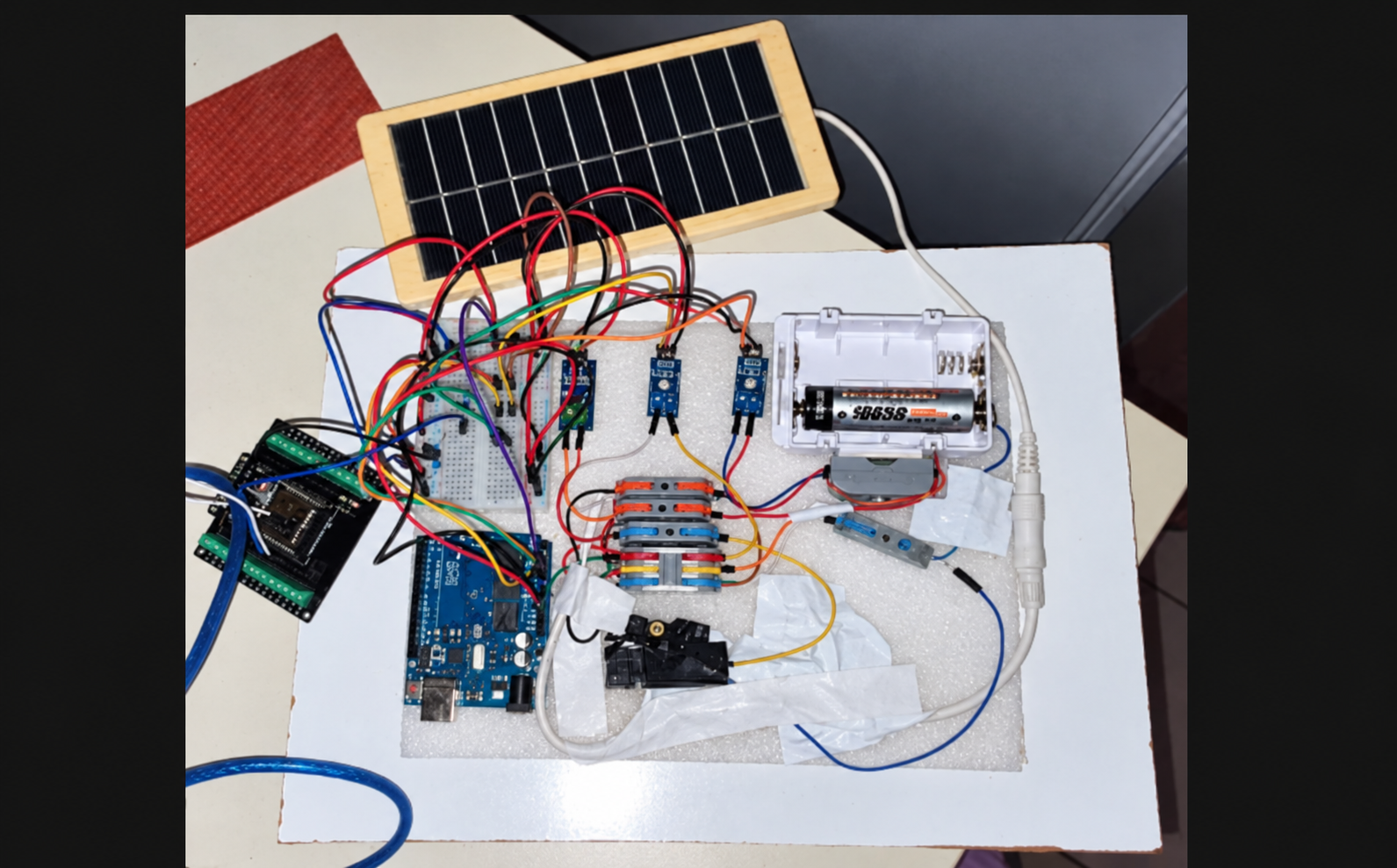
Once I had that data, I could continue with the parts of SolarEase I’d originally planned. I sent the readings to the cloud, stored them, and displayed them in the Android app alongside reports and weather information.
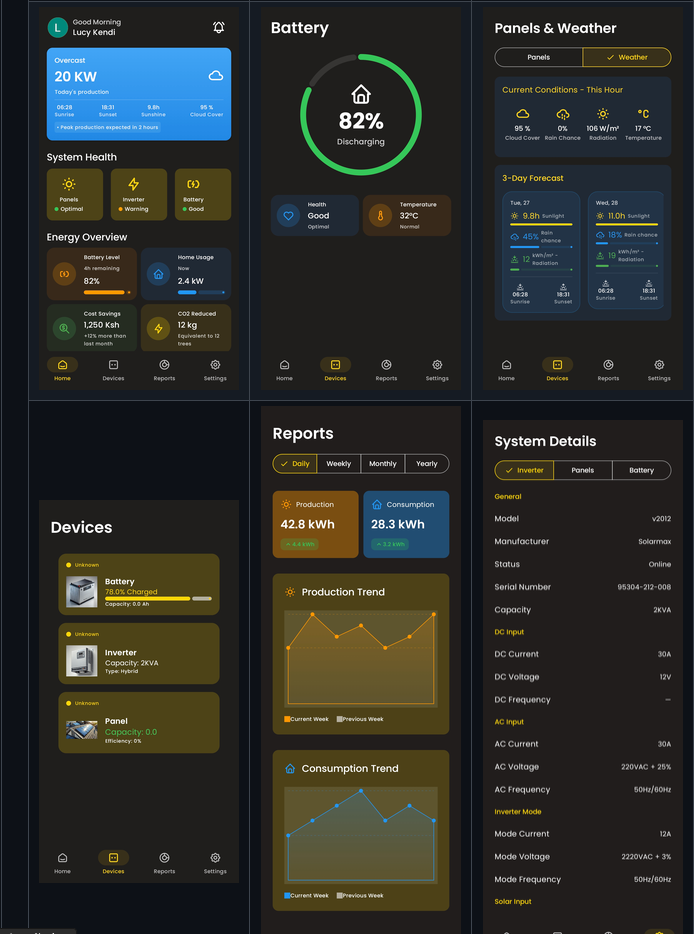
That gave me something I could complete and demonstrate. But it didn’t mean I’d solved the inverter connection. The app was now using readings from my own sensors, not from the equipment I’d originally wanted it to support.
The code and more screenshots are available in the SolarEase repository on GitHub.
What I’d assumed
Looking back, I’d treated access to the data as an early step to get out of the way. Most of my attention had gone to what the app could do once it had the readings.
I wasn’t completely new to this kind of work. I’d done a number of IoT projects before, so connecting sensors, moving data and displaying it somewhere else felt familiar. That gave me some confidence going into SolarEase. What I hadn’t done was try to get data from an existing system like an inverter, where I didn’t control how the information was sent.
I completed the project, but only after changing where the data came from. The app and sensor prototype worked well enough to demonstrate the idea. Connecting reliably to the existing inverters was the part I never finished.
I still think the original idea is worth exploring. I’d just give “get the readings” considerably more space in the plan next time.